3D Animation Graphics
Movicon.NExT
uses XAML graphics with WPF technology which enables you to insert and
use objects with 3D graphics. These objects can be animated by using
individual 3D symbol components and varying the objects observation angle
(camera).

|
Movicon.NExT
has not yet been designed to edit or create 3D graphics scenes
or models Movicon's job is to insert these objects on screens
and provide realtime graphical animation by connecting to the
dynamic Tags to the animation type.
The
Movicon symbol library contains some 3D graphical models, but
the user should provide their own 3D models (generally created
with Cad 3D or simulation software) to import and insert in screens
as preferred.
The
3D format supported by Movicon is XAML and which defines 2D and
3D vector graphics. |
We
shall now look at the basic techniques used for applying graphical animation
to objects. To do this we will use the "NITRO ENGINE"
object from the symbol library as an example to animate the engine's transmission
coupling upon Start-Stop command activation:
Open
an existing screen or add a new one.
Open
the Symbol Gallery and use the mouse click to select the "Refinery"
object from the "3D Symbols" group.
Position
the mouser pointer on an area within screen and click to release and
insert object. Size and position the object as pleased.
Select
the object and access the commands menus by clicking the icon located
on the object's borders and select and activate the "3D
Edit" item.
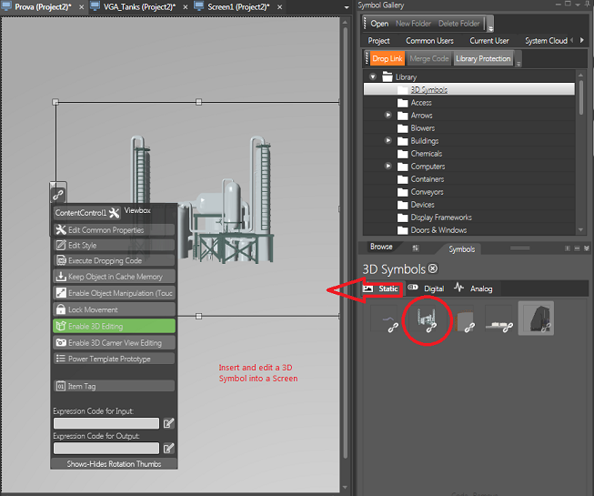
The
"3D Edit" button is available from the Object's Commands Tooltip
Note
that when clicking the various 3D symbol components, the selected
symbol's parts will highlight with a colour and throbbing effect to
show which parts of the 3D symbol the animations refer to.
If the 3D symbol is created with 'Groups
of components',the whole group will be selectable using the
CTRL+Click
command.
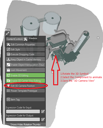
The
3D object can also be rotated also while being edited for either adding
any other components to it or for recording different events viewed
(different 3D camera scene positions), which can then be set in runtime
by the user with a right mouse key click.
When
selecting a symbol component it will animate with a throbbing effect.
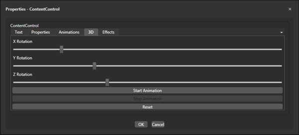
In
addition when the whole object has been selected (and not just one
of its components) you can use the X, Y, Z rotation cursors from the
Common Property Editor's "3D" tab's settings to rotate
the object or perform a simple rotation simulation.
After
having selected the 3D component model desired for animating, use
the object's command menu again and use the "Common
Property Editor" command.
Select
the "Animation"
tab from the dialog window that opens to access the graphical
animation commands available for the individual components
and component groups that compose the the 3D model and which are listed
in the table below:
3D X Angle Rotation |
Object's angle rotation
on X axis in function with tag value |
3D
Y Angle Rotation |
Object's angle rotation
on Y axis in function with tag value |
3D
Z Angle Rotation |
Object's angle rotation
on Z axis in function with tag value |
Back Color |
Back Color based
on tag threshold values |
3D Move X |
Object's linear movement
on the X axis in function with tag value |
3D
Move Y |
Object's linear movement
on the Y axis in function with tag value |
3D
Move Z |
Object's linear movement
on the Z axis in function with tag value |
Scale 3D |
Object's scale sizing
in function with tag value |
Opacity |
Transparency and
visibility value in function with tag value |
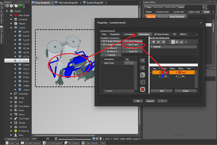
In
our example we will use the animated object's Back Color. Any
other type of graphical animation can be applied by using the same
procedures.
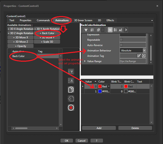
Window
used for selecting Animation type
Go
to the "Animation" window and select the desired dynamic
aniimation command. In this example we will select the "Back
Color" animation.
When
inserting the "Back Color" animation on the list of animations
for the selected component, a window will appear on the right to define
its settings. In this window it will be possible to insert the
colour threshold values by adding the colour thresholds desired to
function with the values that will be obtained by the tag (e.g. 0
= the colour red, 1 = the colour green). It will then be possible
to select the Tag to associate as well as other parameters as seen
with the other dynamic animations.
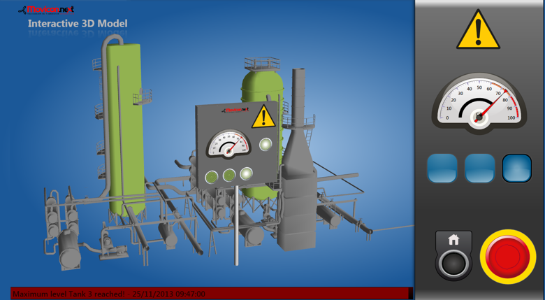
Window
used for setting Y Angle Rotation Animations in 3D
Close
the animation settings window by confirming with "OK".
Take
a "ToggleButton" from the Toolbox and insert it on the screen
to be used for starting and stopping the animation.
Assign
the button with the same tag defined in the animation settings. By
doing this, the 3D object's animation activation tags can be toggles
using this button in Runtime.
At
this point test run this Animation to see if it works by starting
up the project in Runtime and use the button to toggle the tags defined.
The colour of the component selected should animate according
to the tag value.
Inner
Screen Animation
Movicon
provides a very interesting feature called Inner Screen to be used in
3D objects. This feature enables you to manage a whole screen within
the 3D model, which will be placed on the 'face' of the 3D model's components
inserted on screen.
In
this way the associated screen will be displayed within the 3D model and
will be dynamic in both component content representations and command
object interactivity.
Example:
predispose a 600 x 600 pixel sized screen containing a control keypad,
display objects, gauges and start/stop buttons all associated with
the relevant variables. After having accomplished this you can
go ahead and insert this small screen within the 3D model using the
"Inner Screen" tab from the object's Common Property Window
after having selected the 3D component in which the screen is to be
inserted.
When in project runtime it will be possible to rotate the 3D model
and see the 600x600 screen in its position and fully interactive within
the 3D model.
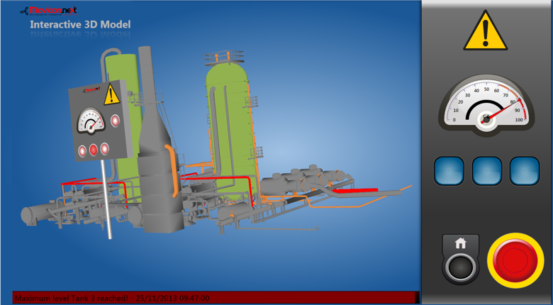
This example
shows how a screen can become an Inner Screen 3D model component. The
screen functions as a 3D Inner Screen positioned and fully interactive
within the model.